BE-IIS-HPP-T1S
Isolated 10BASE-T1S Ethernet for multidrop Single Pair Ethernet evaluation and industrial prototypes.
Overview
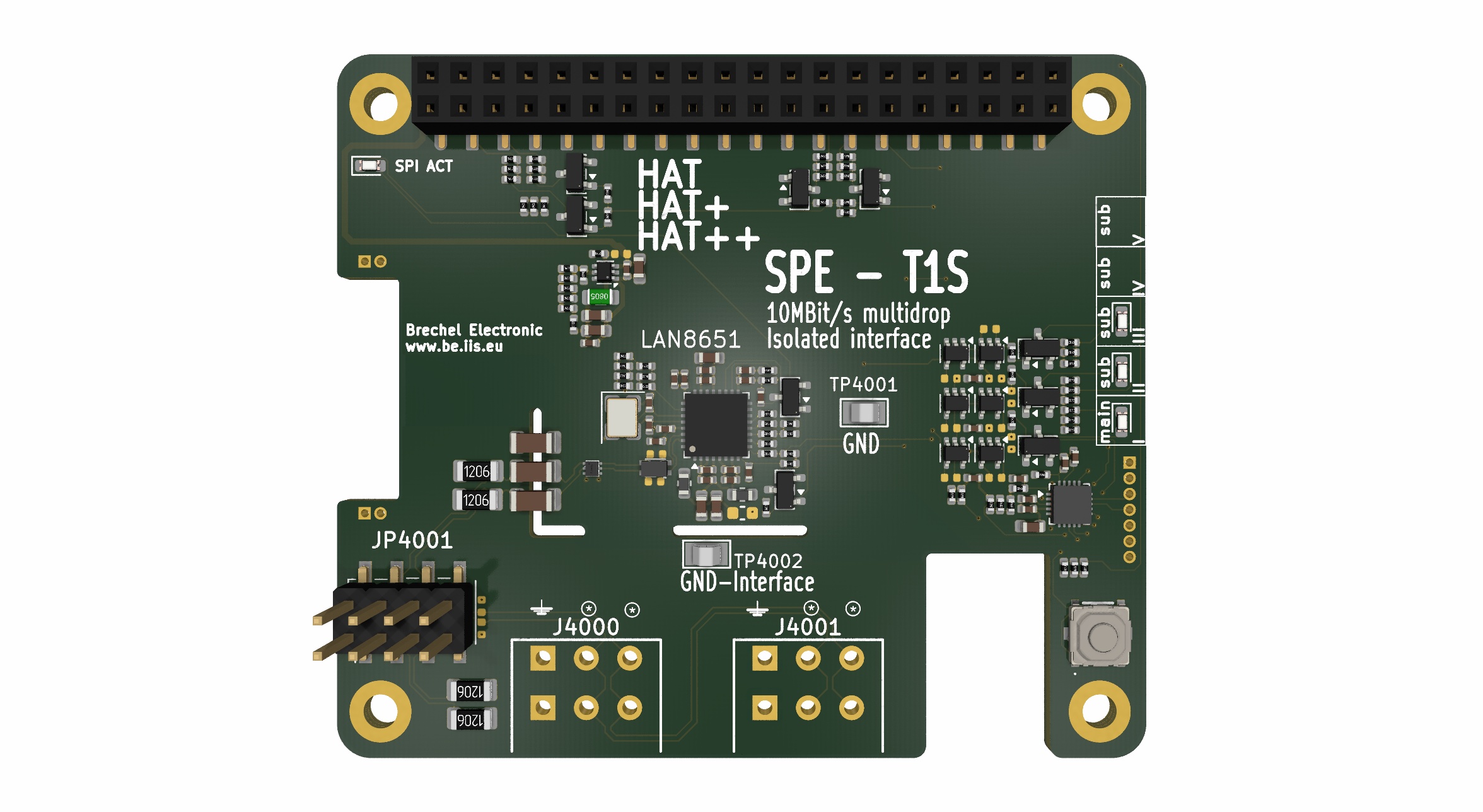
The BE-IIS-HPP-T1S adds 10BASE-T1S Ethernet to a Raspberry Pi. It is based on the Microchip LAN8651 Ethernet MAC-PHY and is intended for multidrop Single Pair Ethernet networks.
10BASE-T1S provides 10 Mbit/s communication over a single twisted pair. It is well suited for evaluating a shared bus with several nodes, rather than the point-to-point topology used by 10BASE-T1L.
Linux integration
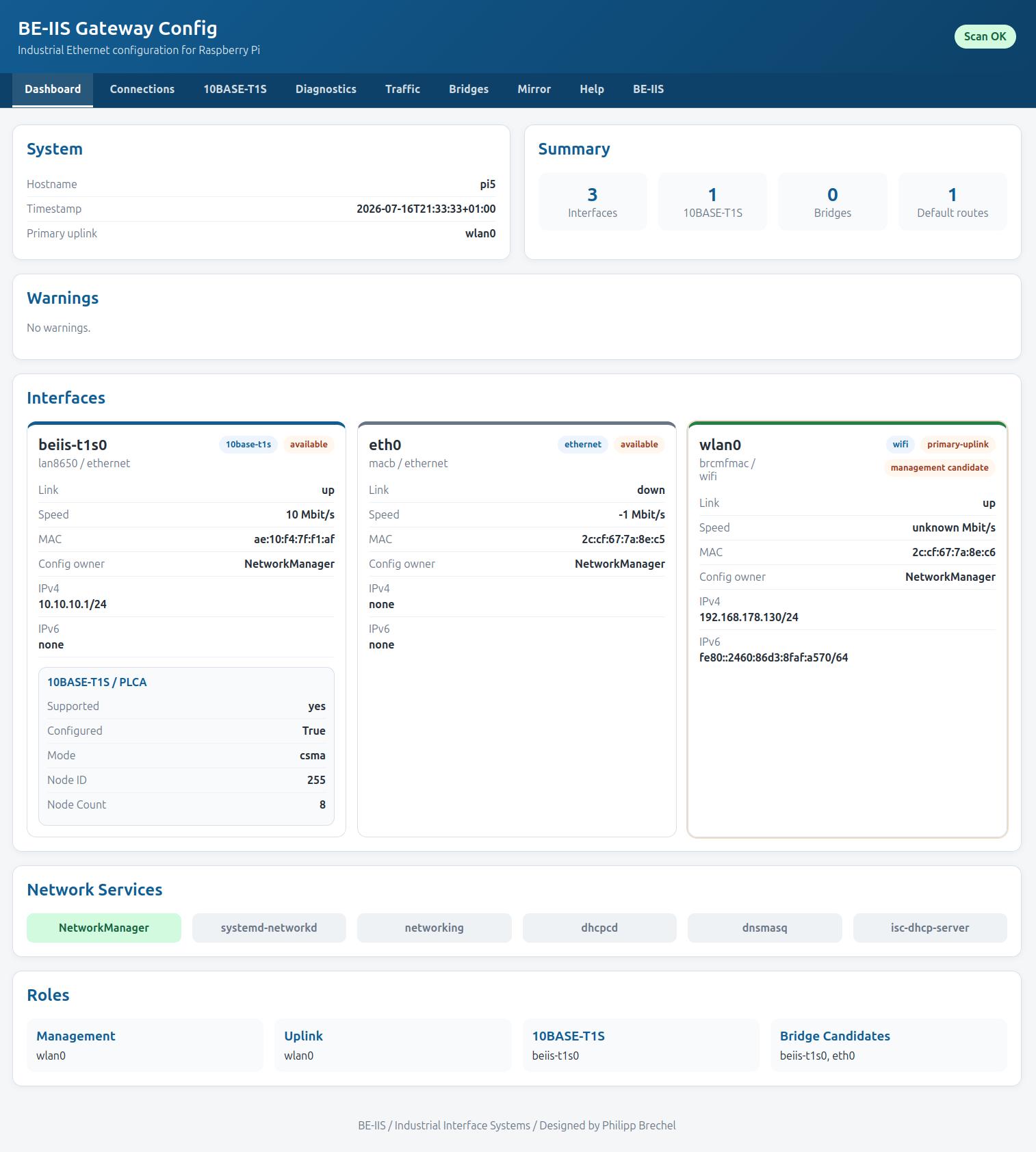
The LAN865x driver communicates with the controller through SPI and uses the OA-TC6 transport layer. The BE-IIS installer loads the required driver modules, installs the selected overlay and provides persistent interface names.
A HAT in instance mode I is normally named beiis-t1s0; the other available instance modes use corresponding persistent names.
PLCA and network setup
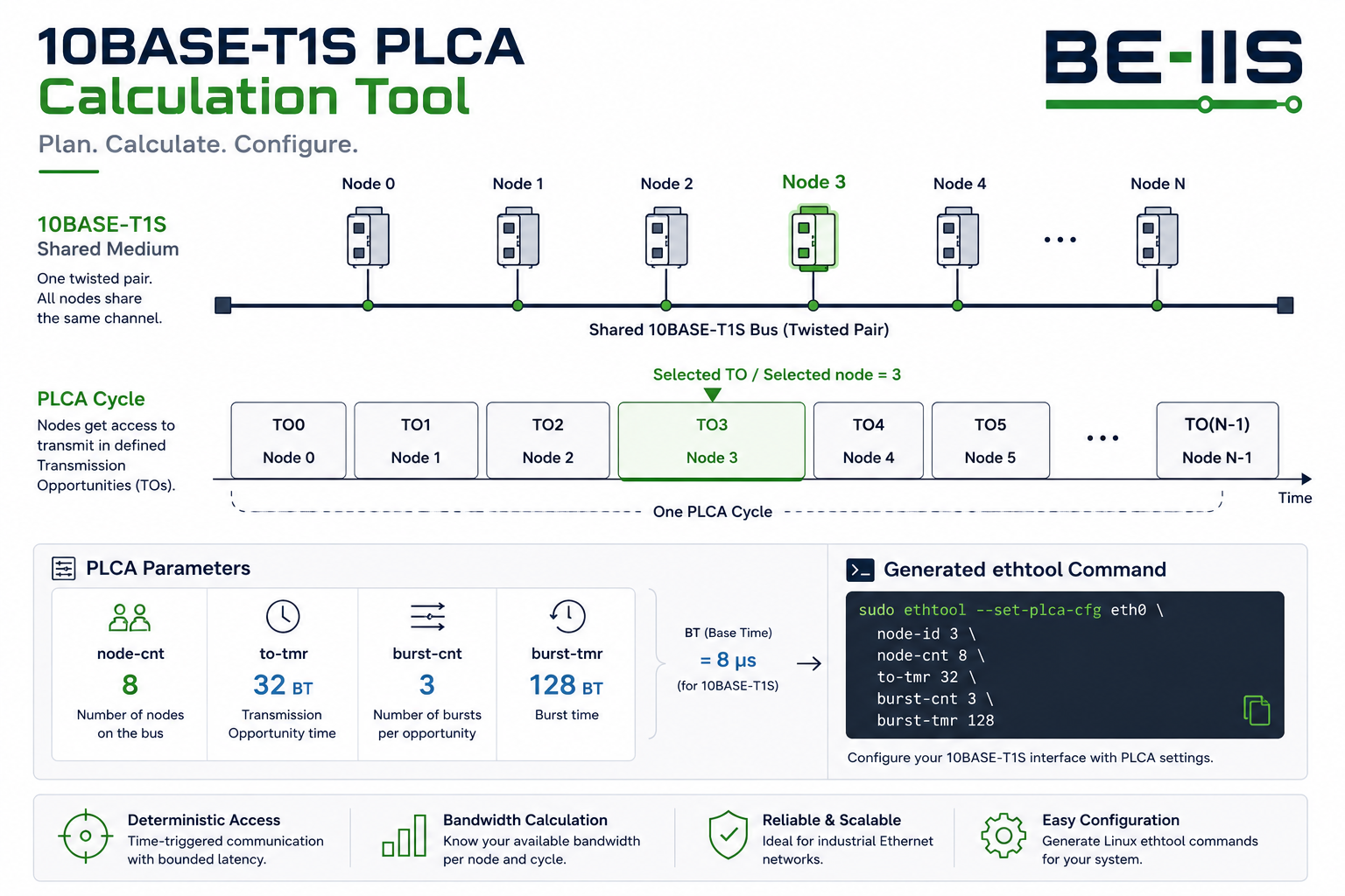
10BASE-T1S uses Physical Layer Collision Avoidance (PLCA) to provide predictable access to the multidrop medium. All nodes on the same segment must use a compatible physical-layer configuration.
Once the interface is present, it is configured with normal Linux networking tools. The board can then be used directly with IPv4, IPv6, UDP, TCP and application protocols such as CAN-over-Ethernet gateways.
PLCA configuration with ethtool
PLCA gives the shared 10BASE-T1S medium a predictable transmit order. All nodes on one segment use the same node count and unique node IDs. In this example, node ID 1 is the PLCA coordinator; the other nodes use IDs 0, 2, 3 and so on.
Read the active configuration:
ethtool --get-plca-cfg beiis-t1s0
Configure the coordinator (node ID 1) for an eight-node segment:
sudo ethtool --set-plca-cfg beiis-t1s0 \
  enable on coord on node-id 1 node-cnt 8 to-tmr 32 burst-cnt 0
A normal node uses the same segment count but has its own ID and does not enable coordinator mode:
sudo ethtool --set-plca-cfg beiis-t1s0 \
  enable on coord off node-id 2 node-cnt 8 to-tmr 32 burst-cnt 0
ethtool --get-plca-cfg beiis-t1s0
Set enable off to return to CSMA/CD access. The PLCA Bandwidth Calculator helps choose the node count and timing. The Linux Command Builder can also generate and explain ethtool PLCA commands.
Two-node PLCA example
The product examples configure distinct PLCA node IDs before assigning addresses. Use unique node IDs on the two devices. If node ID 1 is the coordinator, use node ID 0 for the other endpoint.
sudo ethtool --set-plca-cfg beiis-t1s0 enable on node-id 0 node-cnt 8
sudo ip addr add 10.10.10.1/24 dev beiis-t1s0
sudo ip link set beiis-t1s0 up
The second endpoint uses the same commands with node ID 1 and address 10.10.10.2/24. The repository test scripts automate the full two-node setup:
cd ~/be-iis-installer/products/BE-IIS-HPP-T1S-REVB/test
./test_target1.sh     # node ID 0
./test_target2.sh     # node ID 1
CAN over a 10BASE-T1S link

The CAN-over-TCP bridge in the installer transports Classical CAN and CAN FD frames between two SocketCAN interfaces. A T1S connection provides the IP path between the two Raspberry Pis; the bridge uses TCP port 29536 by default.
After configuring the local CAN interface and the T1S IP connection, start the same program on both systems:
cd ~/be-iis-installer/examples/can-gateway/can-tcp-bridge
./can_tcp_bridge.py 10.10.10.2 beiis-can0    # first gateway
./can_tcp_bridge.py 10.10.10.1 beiis-can0    # second gateway
The gateway with the lower IP address listens automatically; the other one connects. The bridge is bidirectional and keeps CAN frames out of the TCP-to-CAN-to-TCP feedback loop.
Source: CAN TCP Bridge example.
UDP throughput versus SPI clock
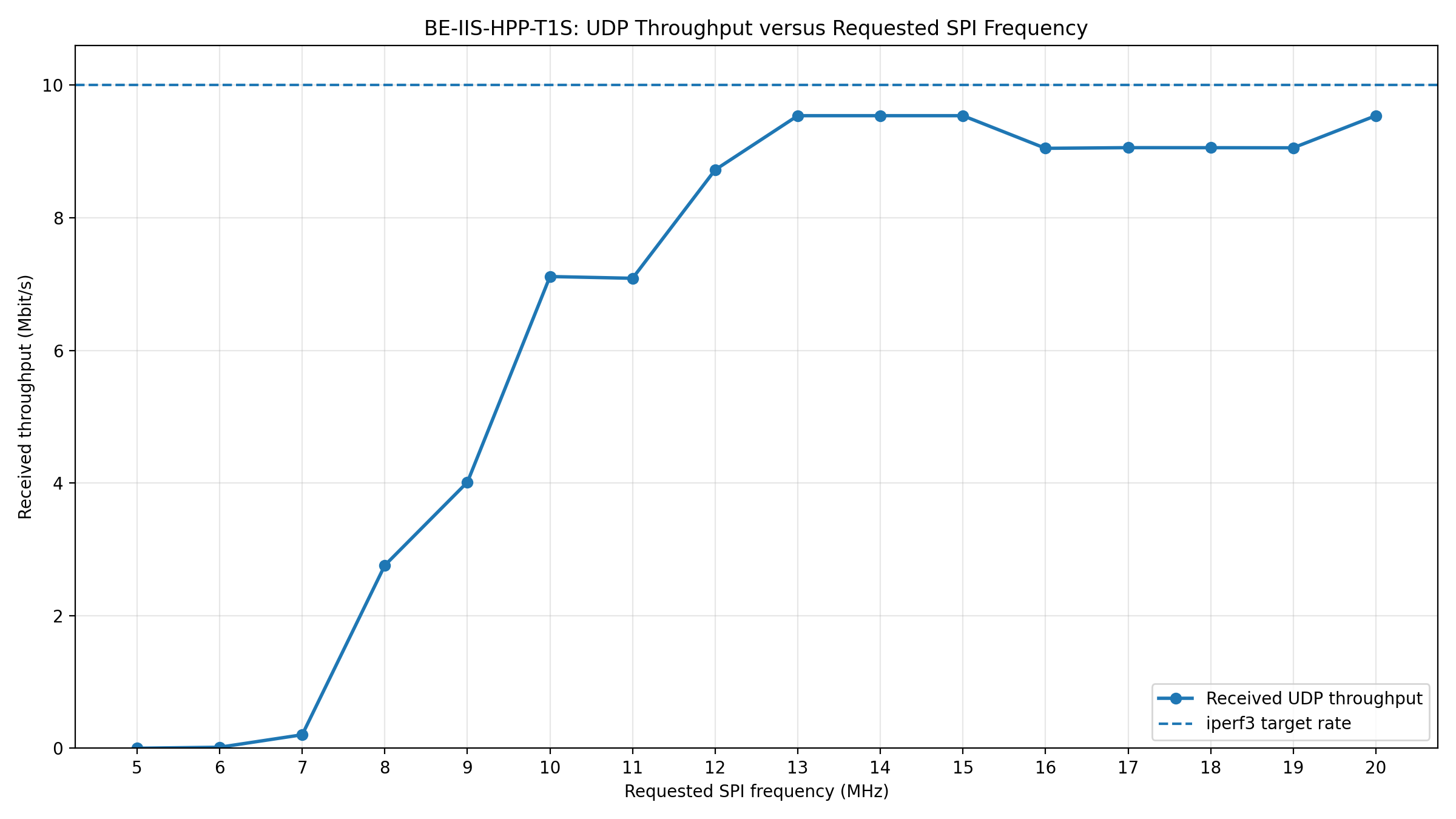
The T1S product documentation includes a measured UDP throughput sweep over the requested SPI clock frequency. It is a practical integration reference: the Ethernet physical layer may operate at 10 Mbit/s, while the SPI connection between Raspberry Pi and MAC-PHY must still be configured appropriately.
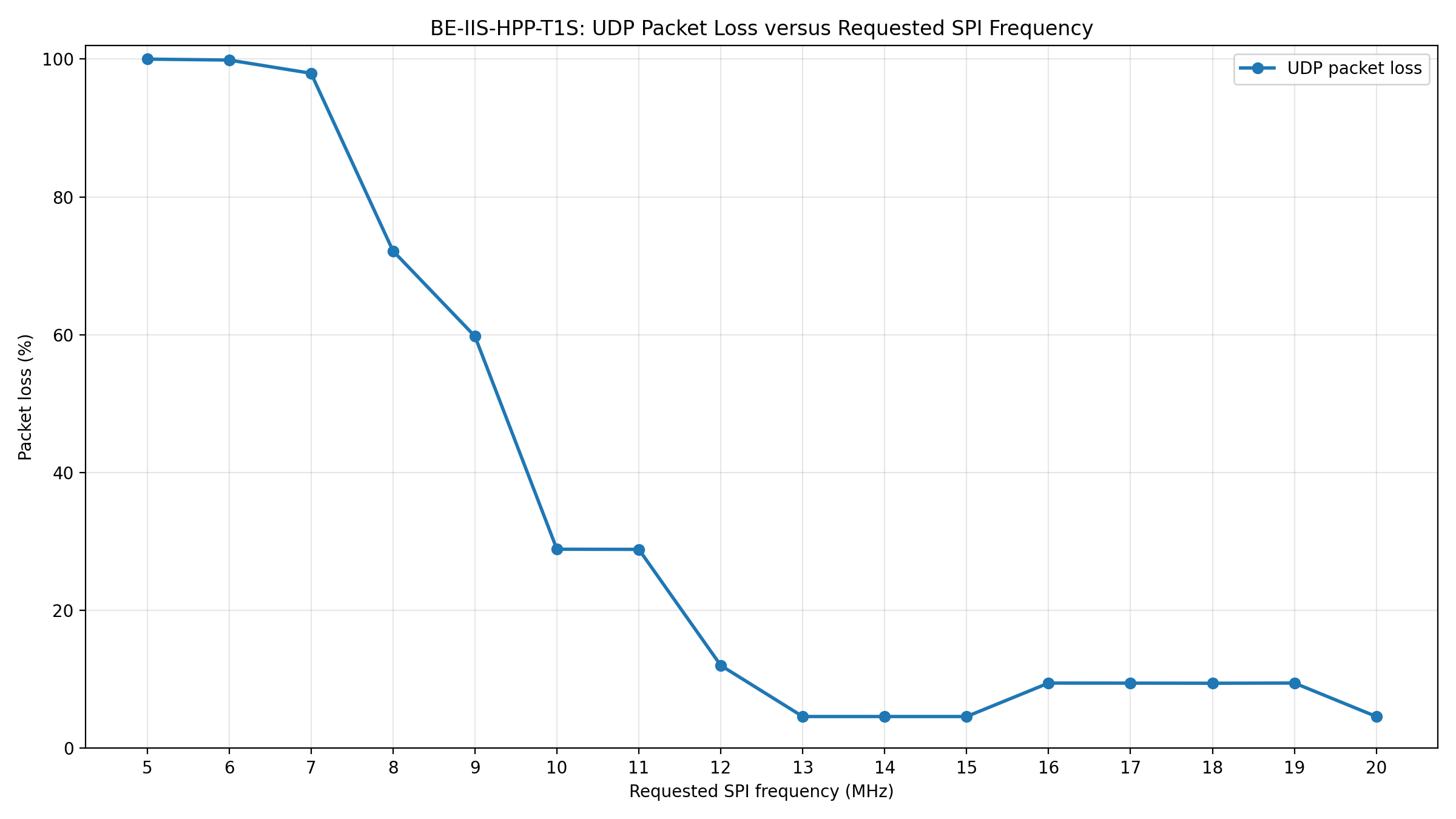
For a reproducible sweep, use the included test directory after two T1S endpoints have been prepared:
cd ~/be-iis-installer/products/BE-IIS-HPP-T1S-REVB/test/pi-speed-sweep
./t1s_spi_sweep.sh
MAC-PHY and SPI throughput
For small UDP packet sizes, the SPI transfer overhead can become the limiting factor before the 10 Mbit/s Ethernet link is saturated. Increase the SPI clock frequency when necessary to reach the required data rate. Verify the result with the actual packet size and traffic pattern used by the application; a setting that is sufficient for large packets may not be sufficient for many small UDP datagrams.
T1L / T1S media converter
A BE-IIS T1L, T1S or 2T1L HAT can be used with the BE-IIS LAN HAT as a transparent Layer-2 media converter between conventional Ethernet and Single Pair Ethernet. The web interface configures the bridge and makes link, PLCA and traffic diagnostics visible. It is Ethernet bridging, not CAN or Modbus protocol conversion.
The T1L/T1S interface converter application explains the complete setup. The implementation and web interface are available in the BE-IIS Network Web repository.