More than a HAT
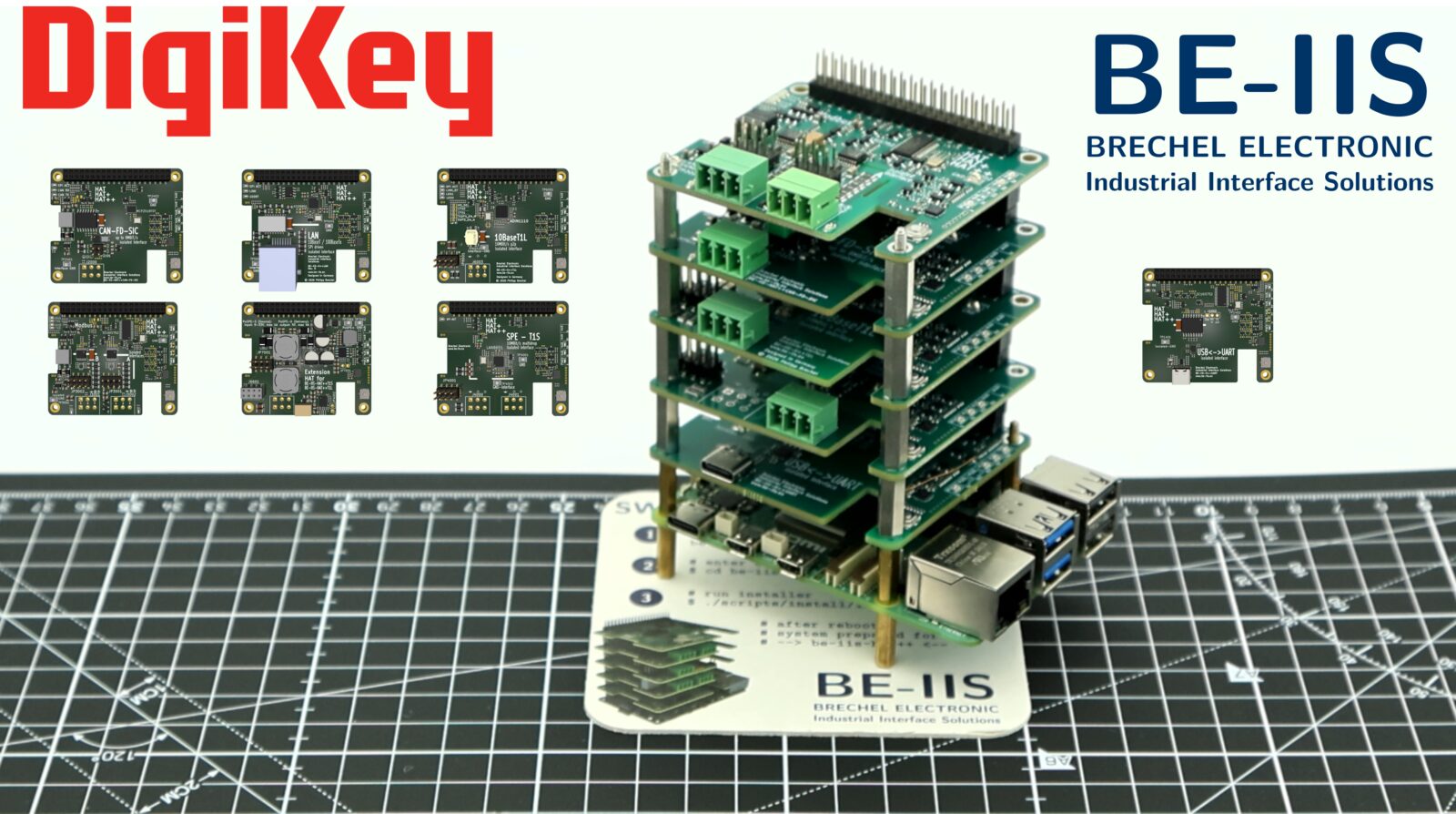
What is this project about?
The Raspberry Pi HAT concept is a very useful way to add one hardware function to a Raspberry Pi.
But many real applications need more than one interface at the same time. A system may need CAN FD, RS-485, 10BASE-T1S, 10BASE-T1L, UART or Ethernet in one setup.
As soon as several HATs are combined, resource conflicts can appear. GPIO pins, SPI chip-selects, I²C addresses, interrupt lines and Device Tree overlays may overlap.
The goal of BE-IIS HAT++ is to make several Raspberry Pi HATs work together in one stack without manual conflict solving.
Why more than one HAT?
The project started with the idea of designing Raspberry Pi HATs for interesting industrial interface technologies.
But during the concept phase, one question became more and more important:
Why should a Raspberry Pi use only one HAT?
The Raspberry Pi becomes much more useful when several functions can be combined. One stack could include CAN FD, RS-485, 10BASE-T1S, 10BASE-T1L, UART or Ethernet interfaces.
That led to the idea of extending the normal Raspberry Pi HAT concept with a simple stacking layer.
The result is what I call HAT++.
The first boards based on this concept have now been developed under the BE-IIS-HPP name.
How does it work?
The basic idea is to give each HAT in the stack a defined instance.
Each instance has assigned hardware resources, such as SPI chip-selects, interrupt lines, I²C addresses and board-specific control signals.
This avoids the typical resource conflicts that can appear when several Raspberry Pi HATs are used together.
A stack needs one board configured as Instance I. Additional boards can be configured as Instance II to Instance V.
Each board knows which signals it is allowed to use in its selected instance mode. This keeps the stack predictable and avoids overlapping chip-select, interrupt and control signals.
Hardware resource assignment
The instance mode is not only a label. It defines which hardware resources a board uses.
Some resources are exclusive to one instance, for example SPI chip-select and interrupt signals. Other resources are shared by all boards in the stack, or by a defined group of instances.
Exclusive resources per instance
| Instance | Chip-select | Interrupt |
|---|---|---|
| Instance I | CSN0 on GP8 | IRQ0 on GP6 |
| Instance II | CSN1 on GP7 | IRQ1 on GP5 |
| Instance III | CSN2 on GP16 | IRQ2 on GP12 |
| Instance IV | — | IRQ3 on GP14 |
| Instance V | — | IRQ4 on GP25 |
Shared hardware resources
The SPI bus signals are shared by Instance I, Instance II and Instance III:
| Signal | GPIO |
|---|---|
| SCLK | GP11 |
| MISO | GP9 |
| MOSI | GP10 |
The reset signal is shared by all instance modes:
| Signal | GPIO |
|---|---|
| RESET | GP13 |
The first I²C bus is shared by all instance modes:
| Signal | GPIO |
|---|---|
| SCL0 | GP1 |
| SDA0 | GP0 |
The second I²C bus is shared by Instance I, Instance IV and Instance V:
| Signal | GPIO |
|---|---|
| SCL1 | GP3 |
| SDA1 | GP2 |
With this assignment, mixed stacks are possible. For example, a stack can be built with three SPI-based boards and two I²C-based boards, or with two SPI-based boards and three I²C-based boards.
Default instance and HAT+ compatibility
Instance I is the default configuration.
In this mode, the board follows the standard Raspberry Pi HAT+ concept and can be detected by the Raspberry Pi during boot.
For this purpose, the board provides HAT identification data on the Raspberry Pi HAT identification bus.
This makes the first board in the stack behave like a normal Raspberry Pi HAT. The additional instance modes are used when more boards are added to the stack.
For the low-level details of the HAT EEPROM and the identification process, refer to the official Raspberry Pi HAT+ specification.
Selecting the instance mode
Additional stackable Raspberry Pi HATs must be moved to another instance mode.
For this purpose, each board has a push button and status LEDs. The LEDs show the currently selected instance mode.
Each board in one stack must use a different instance mode, and at least one board in the stack must be configured as Instance I.
The important detail is that the HAT identification memory is not implemented as a simple fixed-address I²C EEPROM. Instead, this function is handled by a small microcontroller on the board.
When the push button is pressed, the microcontroller changes the selected instance mode. This also changes the I²C address used for the HAT identification data.
Only Instance I uses the standard Raspberry Pi HAT EEPROM address.
| Instance | Identification address |
|---|---|
| Instance I | 0x50 |
| Instance II | 0x60 |
| Instance III | 0x70 |
| Instance IV | 0x74 |
| Instance V | 0x76 |
In addition to the identification address, the microcontroller also controls the board-specific configuration signals.
Depending on the selected instance mode, it selects the required SPI chip-select, interrupt line or I²C address configuration for the controller ICs on the board.
This allows the same board design to be used in different stack positions without changing solder bridges or manually rewiring the hardware.
Loading the additional stack overlays
The Raspberry Pi bootloader detects the first board in the stack through the standard HAT identification address.
Additional boards use different identification addresses. Therefore, they are handled after the normal boot process by a small systemd service.
This service runs once after boot. It iterates over the additional HAT identification addresses, for example 0x60, 0x70, 0x74 and 0x76, and reads the stored HAT data with the Raspberry Pi HAT EEPROM tools.
If valid HAT data is found, the service extracts the overlay name from the EEPROM content and loads the required Device Tree overlay with dtoverlay.
This keeps the normal Raspberry Pi HAT behavior for the first board, while the additional stack boards are added automatically during system startup.
Example integration log:
journalctl -b | grep BE-IIS
BE-IIS Instance I   (0-0050): HAT detected -> BE-IIS-HPP-T1S-I
BE-IIS Instance II  (0-0060): HAT detected -> BE-IIS-HPP-CAN-SIC-II
BE-IIS Instance III (0-0070): HAT detected -> BE-IIS-HPP-LAN-III
BE-IIS Instance IV  (0-0074): HAT detected -> BE-IIS-HPP-UART-II
BE-IIS Instance V   (0-0076): HAT detected -> BE-IIS-HPP-MODBUS-III
BE-IIS HAT++ system integration complete.
Overlay requirements
To make this work, the Device Tree overlays must also be prepared for stacked operation.
Each board overlay exists for the supported instance modes. This is important because the selected instance mode changes which hardware resources are used by the board.
One important rule is that resources must not be occupied by other Linux drivers before the stack overlays are loaded.
If a SPI chip-select is already claimed by spidev, the same resource cannot be reused cleanly by another driver later.
For this reason, the Instance I overlay disables unused spidev devices that would otherwise block chip-select lines required by the stack:
/* Disable spidev on CE1 to keep the second chip-select free for HAT++ use */
fragment@3 {
    target = <&spidev1>;
    __overlay__ {
        status = "disabled";
    };
};
The Instance I overlay also makes the additional HAT identification memories visible on the Raspberry Pi HAT identification bus.
These EEPROM-compatible devices are used by the startup service to detect further boards in the stack.
fragment@9 {
    target = <&i2c0>;
    __overlay__ {
        #address-cells = <1>;
        #size-cells = <0>;

        ee50: eeprom@50 {
            compatible = "atmel,24c32";
            reg = <0x50>;
            status = "okay";
        };

        ee60: eeprom@60 {
            compatible = "atmel,24c32";
            reg = <0x60>;
            status = "okay";
        };

        ee70: eeprom@70 {
            compatible = "atmel,24c32";
            reg = <0x70>;
            status = "okay";
        };

        ee74: eeprom@74 {
            compatible = "atmel,24c32";
            reg = <0x74>;
            status = "okay";
        };

        ee76: eeprom@76 {
            compatible = "atmel,24c32";
            reg = <0x76>;
            status = "okay";
        };
    };
};
With this preparation, the first board still follows the normal Raspberry Pi HAT boot flow.
After boot, the stack integration service can access the additional identification memories, read their overlay strings and load the matching overlays for the other boards in the stack.
This is the point where hardware instance selection, EEPROM-compatible identification memory and Linux overlay handling work together.
Installer and system integration
The basic mechanism is simple:
- emulate a HAT-compatible I²C EEPROM
- store the required overlay information in it
- scan the additional EEPROM addresses after boot
- load the detected Device Tree overlays with Raspberry Pi tools
But the complete system needs more than only the EEPROM logic.
The Raspberry Pi must have the required overlays installed. The systemd service must be configured. The udev rules must be available. Required kernel modules or driver setup steps must also be prepared.
To make this reproducible, the BE-IIS installer provides the required Linux integration files.
The installer can be executed on supported Raspberry Pi systems from Raspberry Pi 1 up to Raspberry Pi 5.
# install git
sudo apt install -y git

# clone installer
git clone https://github.com/be-iis/be-iis-installer.git

# enter directory
cd be-iis-installer

# run installer
./scripts/install/install-all.sh
A successful installation looks like this:
[ INFO ] Installation complete.
[ INFO ] Total scripts : 6
[ INFO ] Successful     : 6
[ INFO ] Failed         : 0
[ INFO ] Changes active after reboot:
[ INFO ] - systemd service
[ INFO ] - udev rules
[ INFO ] - module autoload / runtime setup

Press ENTER to reboot now or CTRL+C to cancel ...
After the reboot, the stack integration service is available. It can scan the additional HAT identification addresses, read the stored overlay strings and apply the matching overlays automatically.
Open and reproducible
All source files required for the Linux integration of the HAT++ system are open and available in the installer repository.
This includes:
- installation scripts
- systemd service
- udev rules
- Device Tree overlays
- board instance integration files
The goal is to keep the system transparent and reproducible.
Anyone interested in the implementation details can inspect the sources, reuse parts of the integration concept or adapt it for their own experiments.
Board status
Current and planned boards in the BE-IIS HAT++ ecosystem:
| Image | Board | Status | Product page | DigiKey |
|---|---|---|---|---|
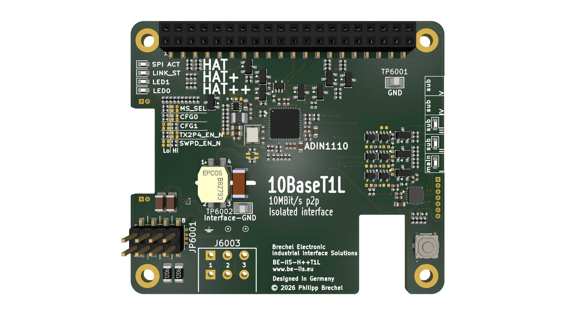 |
BE-IIS-HPP-T1L | available | Product | DigiKey |
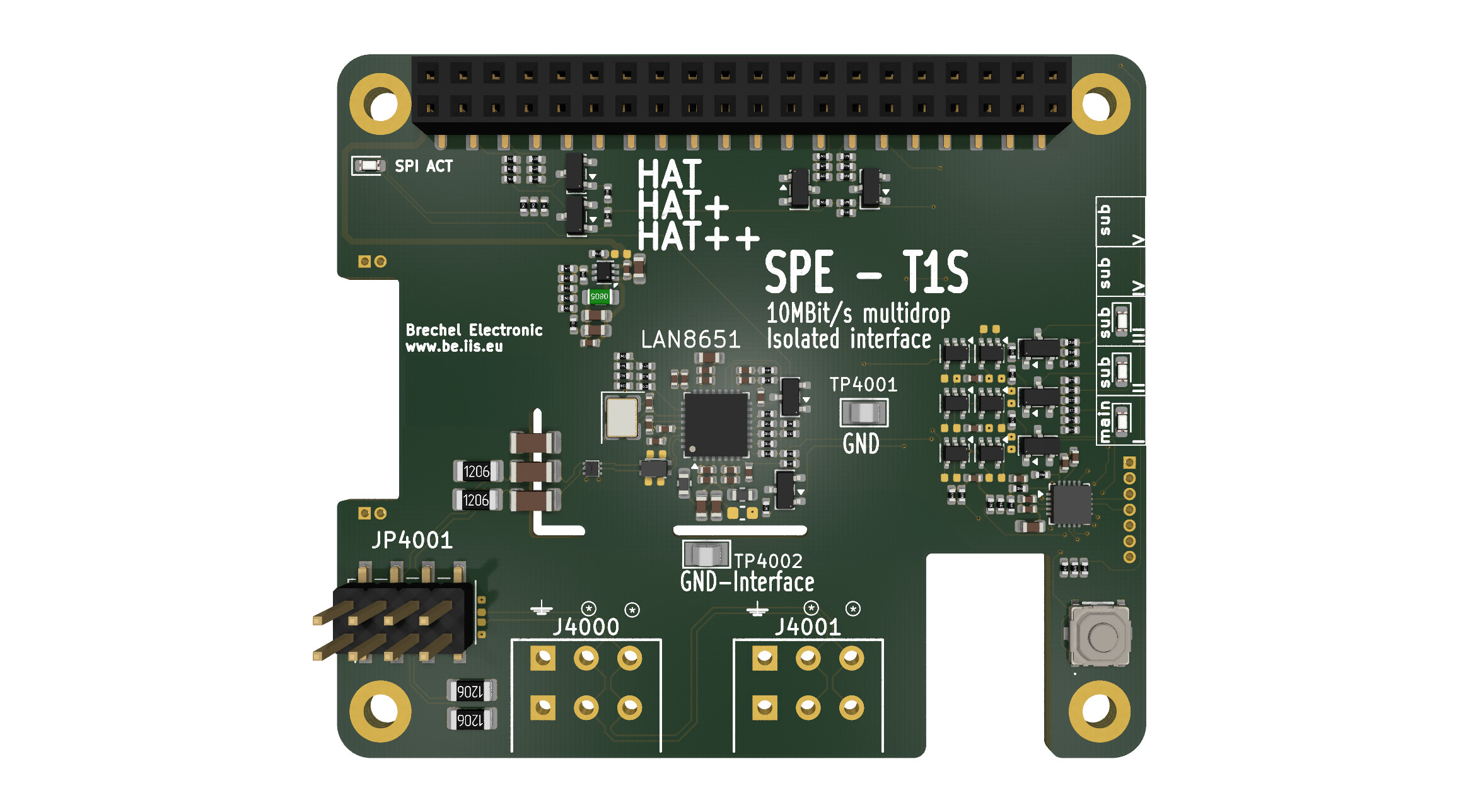 |
BE-IIS-HPP-T1S | available | Product | DigiKey |
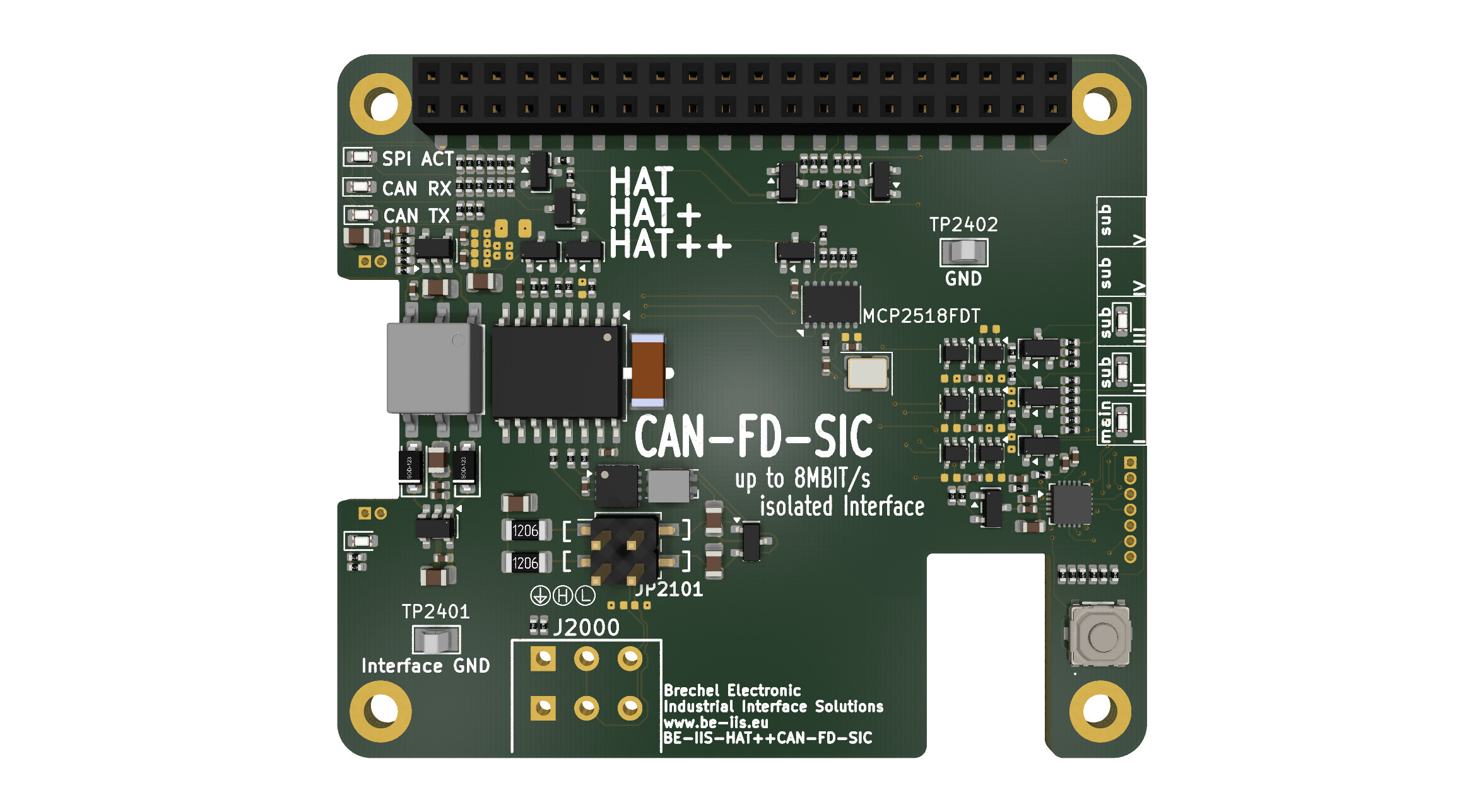 |
BE-IIS-HPP-CAN-FD-SIC | available | Product | DigiKey |
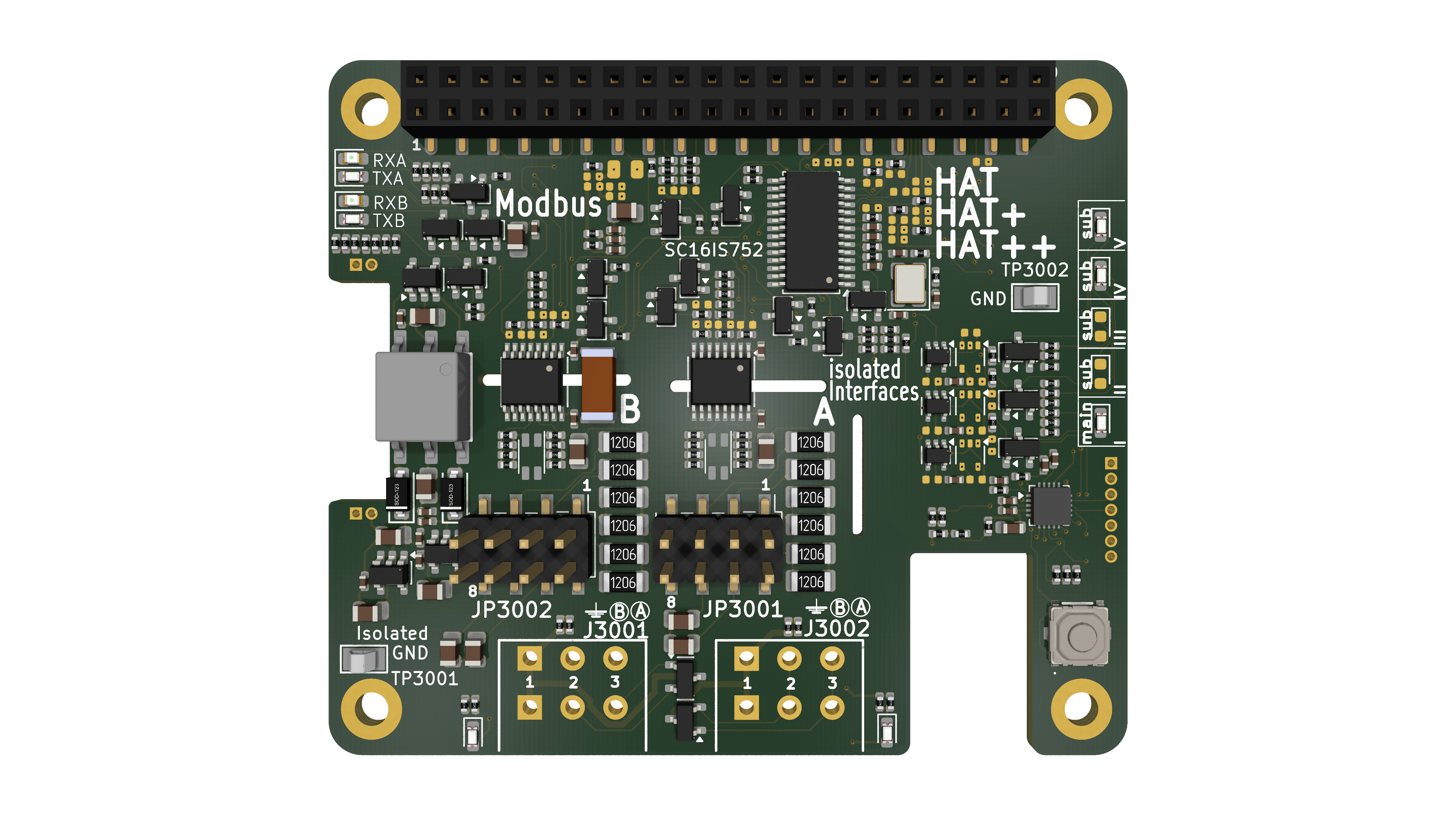 |
BE-IIS-HPP-MODBUS | available | Product | DigiKey |
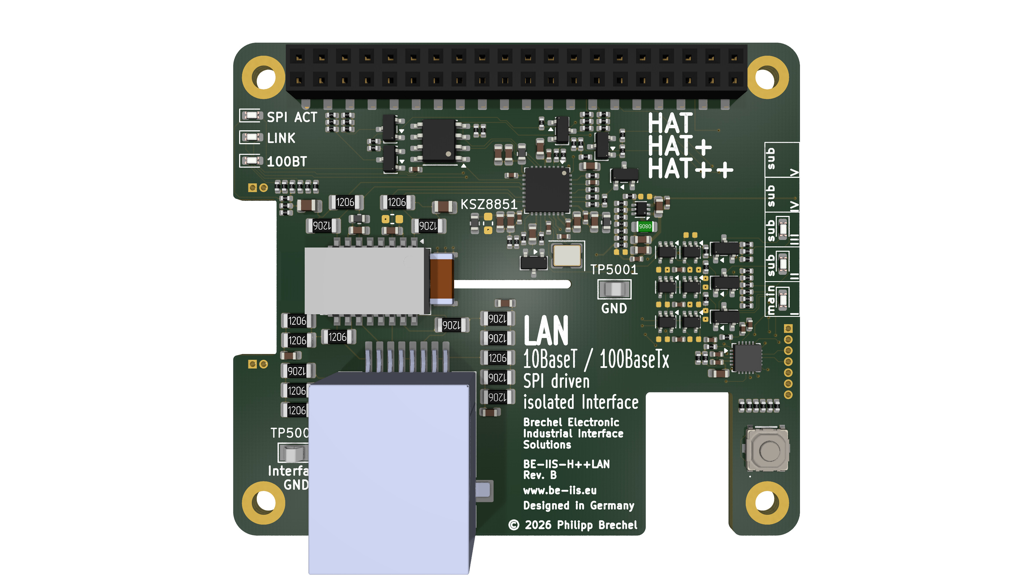 |
BE-IIS-HPP-LAN | in preparation | Product | — |
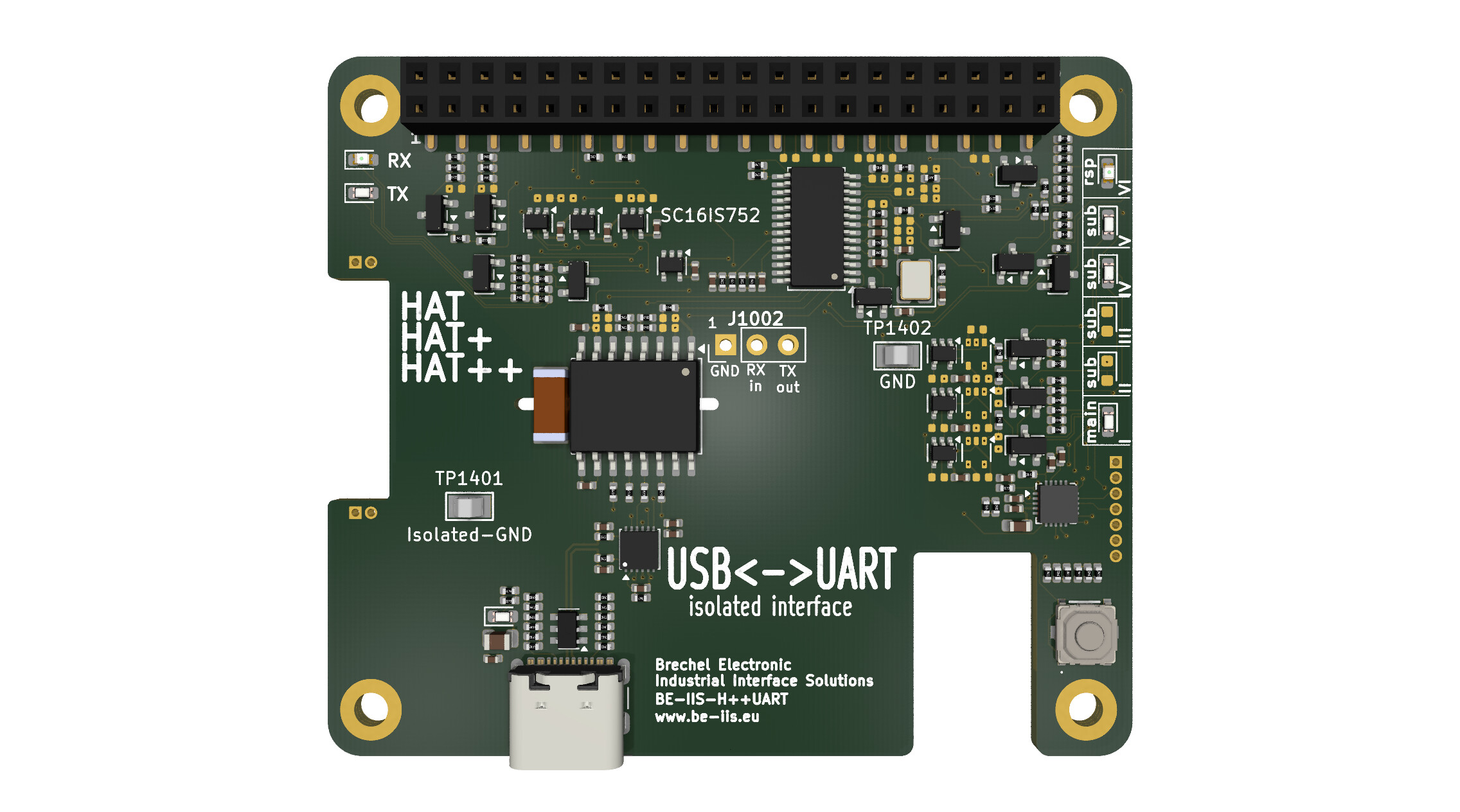 |
BE-IIS-HPP-UART | in preparation | Product | — |
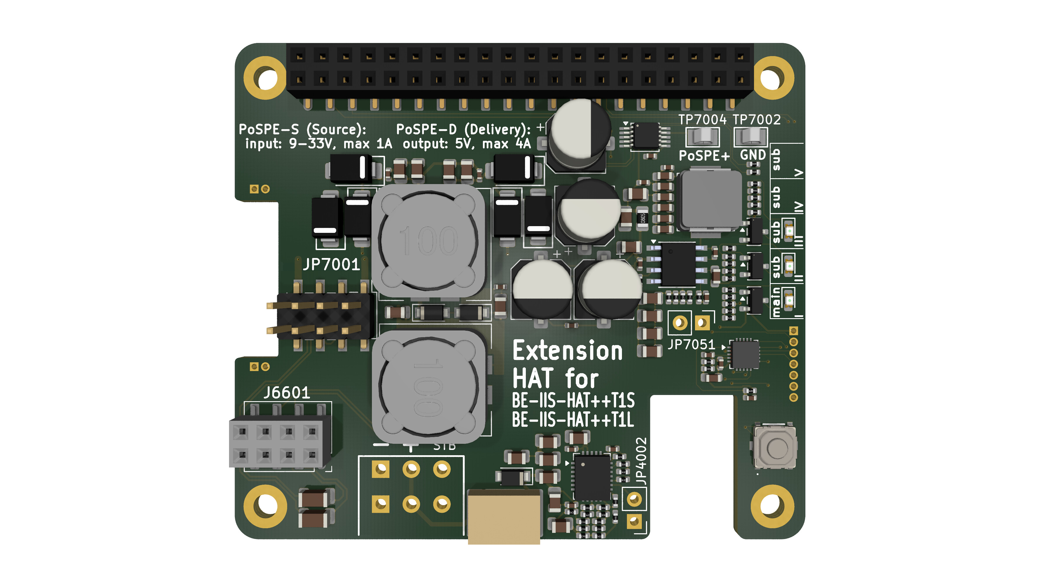 |
BE-IIS-HPP-PoSPE | in preparation | Product | — |
The stacking concept is one important part of the project, but the individual function of each board is also worth presenting.
Each board has its own hardware design, interface technology and use case, for example CAN FD, RS-485, 10BASE-T1S, 10BASE-T1L, UART, Ethernet or Power over Single Pair Ethernet.
Project resources
All Linux integration sources, scripts and Device Tree overlays are open and can be inspected in the installer repository:
- GitHub installer repository: https://github.com/be-iis/be-iis-installer
Additional product resources, such as schematics, datasheets, layout files and 3D models, are available on the project website:
- Website: https://www.be-iis.eu
For readers who want to reproduce the setup with ready-made hardware, selected boards are available through DigiKey:
- DigiKey supplier page: https://www.digikey.de/en/supplier-centers/industrial-interface-solutions
You can also connect with me on LinkedIn:
- LinkedIn: https://www.linkedin.com/in/brechel
Summary
BE-IIS HAT++ is more than a single Raspberry Pi extension board.
It is a stackable hardware and Linux integration concept for combining multiple industrial interface boards on one Raspberry Pi.
The goal is simple: make hardware stacking predictable, make Linux integration reproducible, and keep the system open enough to understand, modify and extend.