BE-IIS-HPP-T1L 10BASE-T1L Test over 100 m YV Cable
10BASE-T1L (IEEE 802.3cg) enables 10 Mbit/s Ethernet communication over a single twisted pair for long-reach point-to-point links.
The BE-IIS-HPP-T1L enables 10BASE-T1L communication based on the Analog Devices ADIN1110 Ethernet MAC-PHY and, as part of the BE-IIS HAT++ ecosystem, is stackable with other HATs from the portfolio for seamless system expansion and simplified system integration.
Key Features
- IEEE 802.3cg compliant 10BASE-T1L interface
- ADIN1110 10BASE-T1L MAC-PHY
- Galvanically isolated MDI interface
- Raspberry Pi HAT+ compliant (2024)
- Stackable HAT design for the BE-IIS HAT++ ecosystem
- Configurable chip-select and IRQ routing
- Optional PoSPE companion-board support
- RoHS compliant
- Components from established quality suppliers
Hardware Test Setup
For this test, two Raspberry Pi systems are connected directly over a 10BASE-T1L point-to-point link.
The setup uses:
- 1 × Raspberry Pi 5
- 1 × Raspberry Pi Zero 2 W
- 2 × BE-IIS-HPP-T1L HATs
- 1 × single twisted pair cable (YV 2×0.6/1.1, 100 m)
Both Raspberry Pi systems are equipped with one BE-IIS-HPP-T1L HAT.
For this simple point-to-point test, both HATs are configured in Instance Mode 0.
Raspberry Pi 5
+ BE-IIS-HPP-T1L
        |
        | 10BASE-T1L single twisted pair
        |
Raspberry Pi Zero 2 W
+ BE-IIS-HPP-T1L
This creates a direct 10BASE-T1L Ethernet link between the two Raspberry Pi systems.
Software Test Setup
Both Raspberry Pi systems run Raspberry Pi OS 64-bit.
The 64-bit version is used because the ADIN1110 driver requires the Linux switchdev infrastructure when built as a loadable kernel module. In this setup, the required kernel option CONFIG_NET_SWITCHDEV is available in the 64-bit Raspberry Pi OS kernel, but not in the ARM 32-bit kernel.
After installing the BE-IIS software package, the required driver module, device tree overlay, and interface configuration are applied by the BE-IIS installer.
Clone the Repository
git clone https://github.com/be-iis/be-iis-installer.git
Run the Installer
cd be-iis-installer
./scripts/install/install-all.sh
[INFO] Done
[INFO] Total scripts : 6
[INFO] Successful    : 6
[INFO] Failed        : 0

[INFO] --------------------------------------------------
[INFO] Installation complete.
[INFO] The following changes will become active after reboot:
[INFO]   - systemd service
[INFO]   - udev rules
[INFO]   - module autoload / runtime setup
[INFO] --------------------------------------------------

Press ENTER to reboot now or CTRL+C to cancel...
The installation must be performed on both Raspberry Pi systems.
Verify System Integration
After reboot, the BE-IIS system integration log can be checked with:
journalctl -b | grep "BE-IIS"
Example output on the Raspberry Pi Zero 2 W:
BE-IIS ========================================
BE-IIS HAT++ System Integration
BE-IIS ========================================
BE-IIS [1/2] Scanning BE-IIS HAT++ EEPROMs...
BE-IIS Instance I (0-0050): HAT detected → BE-IIS-HPP-T1L-I
BE-IIS Instance I (0-0050): Base instance (overlay handled by HAT+ autodetect)
BE-IIS [2/2] Loading BE-IIS kernel modules...
BE-IIS Loading module: adin1110
BE-IIS HAT++ system integration complete.
The log shows that the BE-IIS-HPP-T1L was detected as Instance I and that the base overlay was handled by the Raspberry Pi HAT+ autodetection mechanism.
The T1L network interface is available as:
ifconfig beiis-t1l0
Example output:
beiis-t1l0: flags=4163<UP,BROADCAST,RUNNING,MULTICAST>  mtu 1500
        inet6 fe80::54cc:d24a:c28:6595  prefixlen 64  scopeid 0x20<link>
        ether 02:00:bb:00:00:02  txqueuelen 1000  (Ethernet)
        RX packets 6  bytes 384
        TX packets 50  bytes 9159
        TX errors 0  dropped 2 overruns 0  carrier 0  collisions 0
This confirms that the 10BASE-T1L interface was created successfully and is available as a normal Linux Ethernet interface.
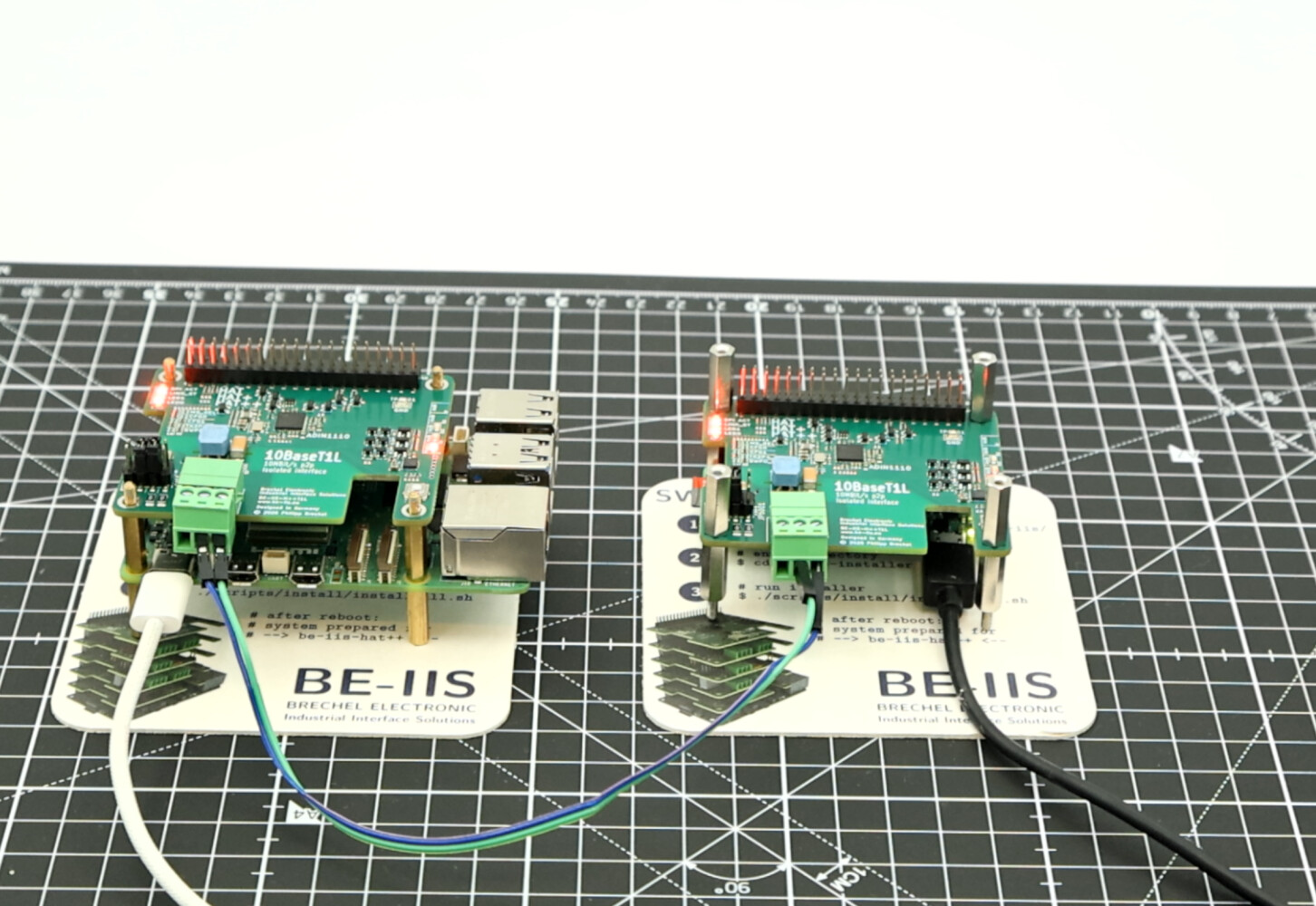
First Functional Test: Short Lab Connection
For the first functional test, the BE-IIS product test scripts are used.
The two BE-IIS-HPP-T1L boards are connected directly with a short 10 cm cable. This is a simple lab setup and not a specified 10BASE-T1L test cable.
One Raspberry Pi starts the target-side test script and runs the iperf3 server:
cd ~/be-iis-installer/products/BE-IIS-HPP-T1L-REVB/test
./test_target2.sh
The second Raspberry Pi runs the main test script:
cd ~/be-iis-installer/products/BE-IIS-HPP-T1L-REVB/test
./test_target1.sh
The scripts configure the 10BASE-T1L interface beiis-t1l0 and assign the following IP addresses:
Test target 1: 10.10.10.1
Test target 2: 10.10.10.2
After the initial link setup, the ping test confirms the point-to-point connection:
64 bytes from 10.10.10.2: icmp_seq=5 ttl=64 time=0.939 ms
64 bytes from 10.10.10.2: icmp_seq=6 ttl=64 time=0.963 ms
64 bytes from 10.10.10.2: icmp_seq=7 ttl=64 time=0.956 ms
The TCP iperf3 test reaches about 9.3 Mbit/s on the receiver side:
TCP iperf3 result:
11.1 MBytes received in 10.03 s
9.31 Mbits/sec receiver bitrate
A UDP iperf3 test with a 10 Mbit/s target rate was also performed:
UDP iperf3 result:
11.4 MBytes received in 10.01 s
9.56 Mbits/sec receiver bitrate
4.2% packet loss
The product test completed successfully:
[TEST] SUCCESS
This confirms that the BE-IIS-HPP-T1L establishes a working 10BASE-T1L Ethernet link and can be used as a normal Linux network interface between two Raspberry Pi systems.
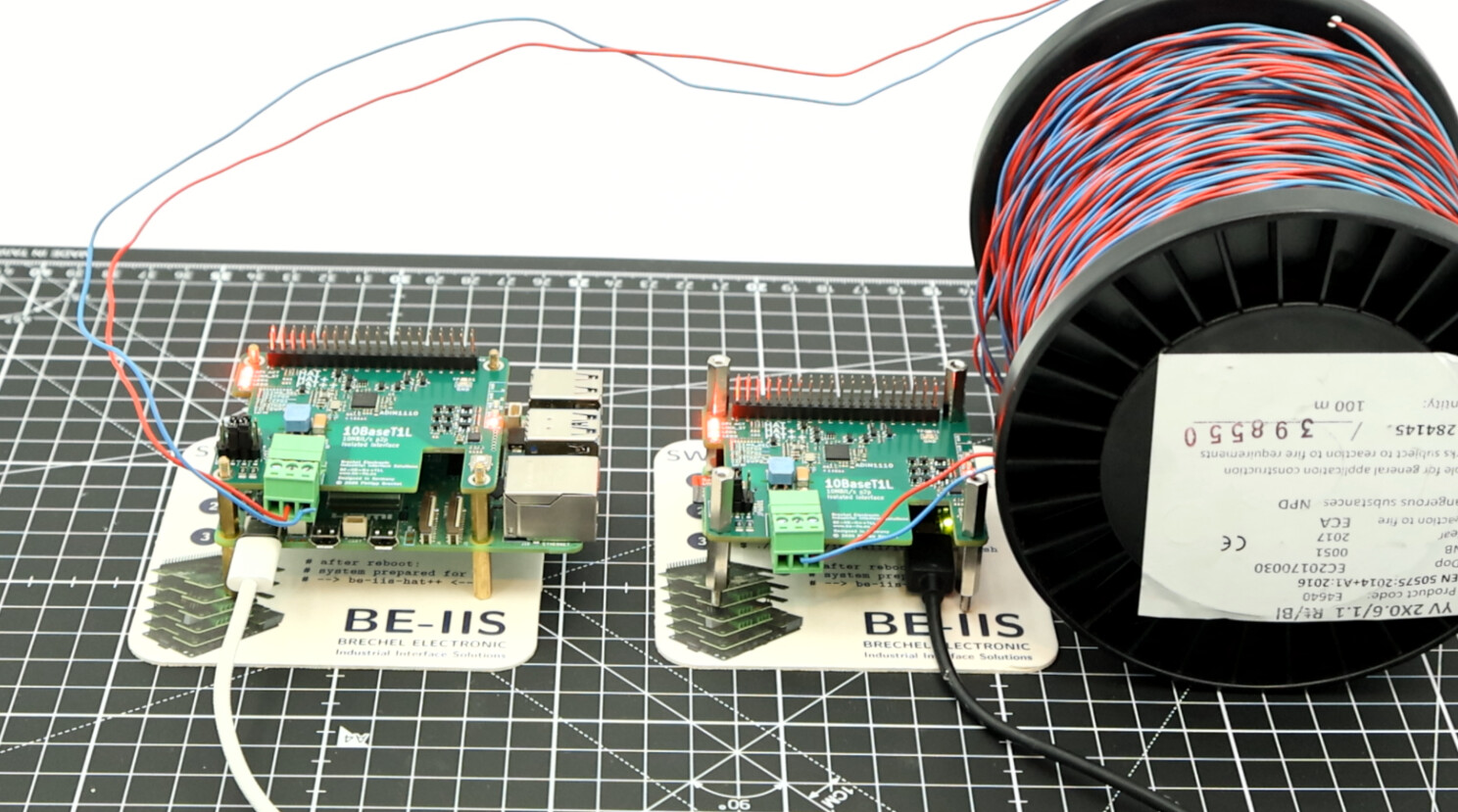
Second Functional Test: 100 m YV 2×0.6/1.1 Cable
For the second functional test, the same BE-IIS product test scripts are used.
The two BE-IIS-HPP-T1L boards are connected directly with a 100 m YV 2×0.6/1.1 cable. This is a practical cable test and not a specified 10BASE-T1L reference cable.
One Raspberry Pi starts the target-side test script and runs the iperf3 server:
cd ~/be-iis-installer/products/BE-IIS-HPP-T1L-REVB/test
./test_target2.sh
The second Raspberry Pi runs the main test script:
cd ~/be-iis-installer/products/BE-IIS-HPP-T1L-REVB/test
./test_target1.sh
The scripts configure the 10BASE-T1L interface beiis-t1l0 and assign the following IP addresses:
Test target 1: 10.10.10.1
Test target 2: 10.10.10.2
The ping test confirms the point-to-point connection over the 100 m cable:
10 packets transmitted, 10 received, 0% packet loss
rtt min/avg/max/mdev = 0.807/2.761/19.379/5.539 ms
The TCP iperf3 test reaches about 9.3 Mbit/s on the receiver side:
TCP iperf3 result:
11.1 MBytes received in 10.02 s
9.32 Mbits/sec receiver bitrate
A UDP iperf3 test with a 10 Mbit/s target rate was also performed:
UDP iperf3 result:
11.4 MBytes received in 10.01 s
9.56 Mbits/sec receiver bitrate
4.2% packet loss
The product test completed successfully:
[TEST] SUCCESS
This confirms that the BE-IIS-HPP-T1L establishes a working 10BASE-T1L Ethernet link over 100 m YV 2×0.6/1.1 cable and can be used as a normal Linux network interface between two Raspberry Pi systems.
Conclusion
The test shows that the BE-IIS-HPP-T1L can establish a stable 10BASE-T1L point-to-point Ethernet link between two Raspberry Pi systems.
The first test used a short 10 cm lab connection. The second test used a 100 m YV 2×0.6/1.1 cable.
YV 2×0.6/1.1 is not a specified 10BASE-T1L reference cable. It is normally used as simple switching, ringing, signalling, or telecommunication installation wire.
This makes the result interesting: even with this simple cable type, the link came up successfully, ping worked without packet loss, and TCP iperf reached about 9.3 Mbit/s on the receiver side.
The UDP test was performed with a 10 Mbit/s target rate. The receiver reported about 9.56 Mbit/s and around 4.2% packet loss.
This packet loss is most likely caused by the UDP test being close to or slightly above the practical payload limit of a 10 Mbit/s Ethernet link. UDP does not reduce its rate automatically and does not retransmit lost packets. In addition, protocol overhead must also be transmitted on the wire. Therefore, a 10 Mbit/s UDP payload target can overload a 10 Mbit/s physical link.
For this reason, the UDP packet loss should not be interpreted as a failed link. The more important result is that the 100 m link was established successfully, TCP communication worked close to the expected 10BASE-T1L data rate, and the product test completed with:
[TEST] SUCCESS
The test does not replace formal compliance testing with specified 10BASE-T1L cabling. But it demonstrates that the BE-IIS-HPP-T1L can be used for practical Raspberry Pi based 10BASE-T1L evaluation, prototyping, and lab setups over longer single-pair cable connections.
Links and References
Product page, including datasheet, schematic, PCB layout, and 3D data: https://www.be-iis.eu/products/BE-IIS-HPP-T1L_B/
BE-IIS installer on GitHub: https://github.com/be-iis/be-iis-installer/
DigiKey product page: https://www.digikey.de/en/products/detail/brechel-electronic-industrial-interface-systems-be-iis/BE-IIS-HPP-T1L/29436903